Security Horn Circuit
THEFT DETERRENT: THEFT DETERRENT SYSTEM (w/ Smart Key System): Security Horn Circuit
- Security Horn Circuit
DESCRIPTION
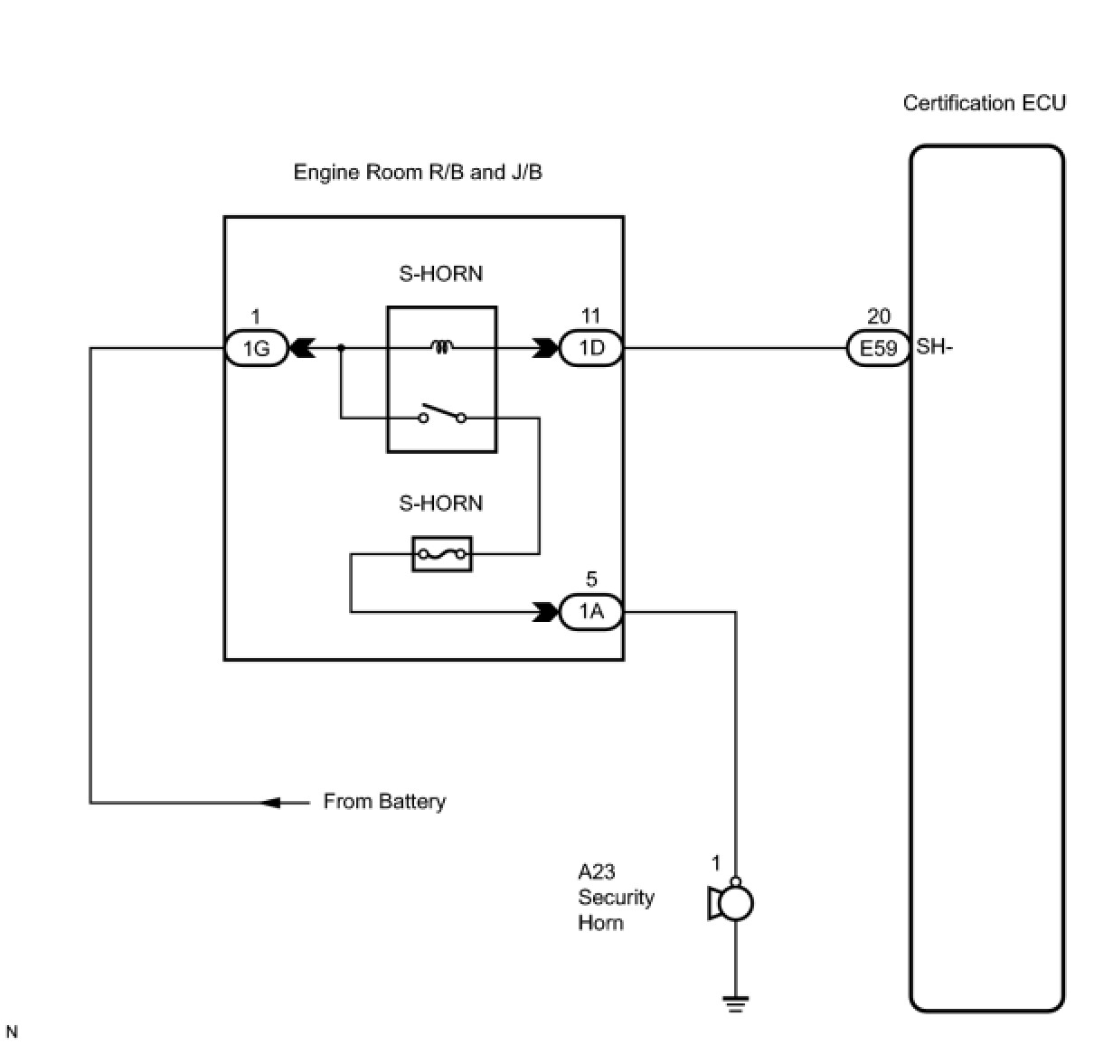
When the theft deterrent system is changed from the armed state to the alarm sounding state, the certification ECU can control the security horn.
WIRING DIAGRAM
INSPECTION PROCEDURE
PROCEDURE
1. INSPECT SECURITY HORN ASSEMBLY
(a) Remove the security horn assembly.

(b) Check operation of the horn.
Standard:

NG -- REPAIR OR REPLACE SECURITY HORN ASSEMBLY
OK -- Continue to next step.
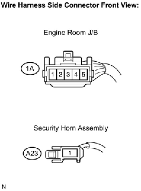
2. CHECK HARNESS AND CONNECTOR (ENGINE ROOM J/B - SECURITY HORN ASSEMBLY)
(a) Disconnect the 1A J/B connector and the A23 horn connector.
(b) Measure the resistance according to the value(s) in the table below.
Standard resistance:

NG -- REPAIR OR REPLACE HARNESS OR CONNECTOR
OK -- Continue to next step.
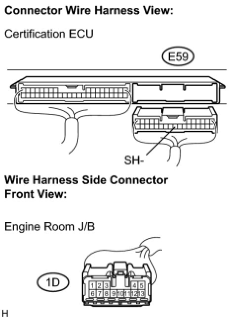
3. CHECK HARNESS AND CONNECTOR (CERTIFICATION ECU - ENGINE ROOM J/B)
(a) Disconnect the E59 ECU connector and 1D J/B connector.
(b) Measure the resistance according to the value(s) in the table below.
Standard resistance:

NG -- REPAIR OR REPLACE HARNESS OR CONNECTOR
OK -- Continue to next step.
4. CHECK HARNESS AND CONNECTOR (ENGINE ROOM J/B - BATTERY)
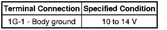
(a) Disconnect the 1G J/B connector.

(b) Measure the voltage according to the value(s) in the table below.
Standard voltage:
NG -- REPAIR OR REPLACE HARNESS OR CONNECTOR
OK -- PROCEED TO NEXT CIRCUIT INSPECTION SHOWN IN PROBLEM SYMPTOMS TABLE